If I put the multimeter over on pins Q1 and Q2 on the module these are the wires that connect to the motor, it says 1.76 Volts.
So there appears to be some voltage present when the blind motor is not in motion.
If I put the multimeter over on pins Q1 and Q2 on the module these are the wires that connect to the motor, it says 1.76 Volts.
So there appears to be some voltage present when the blind motor is not in motion.
And voltage when button is pressed?
About 11.92 volts when I press the wall switch and the blind moves.
If I press the switch the other way then its -11.92 etc.
Ok Think i understand now
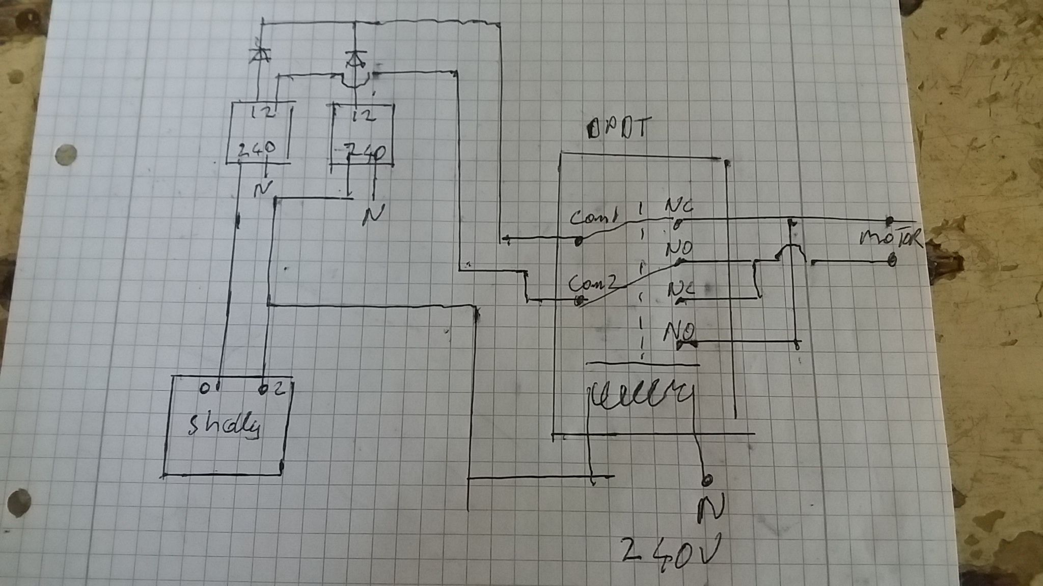
This can be done with shelly 2.5 or fibaro
you would need 2 - 240v to 12v dc transformers and a 240v dpdt relay and some diodes for transformer 12v side to stop feed back.
here is rough lay out wiring sketch
OK thanks, so it might be possible then. If this new Qubino DC module from Vesternet doesn’t work either then I may have to do something like that or the only other option is to swap out the 12V DC motor.
In the final installation I don’t plan to use a wall switch just control it via Z-Wave etc.
This can be done also with 1 DPDT and 1 SPDT relay and 1 transformer, you could combine the relays and use a 3 pole relay but you would be mixing voltages, and certain fault in relay could put 240 across motor, Keeping relays seperate is fail safe.
I have a similar relay from Amazon, switching from 12v to 12/220v ac/dc. It’s taking +/- as input and giving separate l/n as output. I’m using it to correct -/+ for a Shelly 1 v12, maybe there’s a similar route. The relays are separated, but on the same board. Just an extra path.
I’ve got a brand new Qubino DC Flush Shutter module (Software 7 Firmware) to replace the older Software 5 Firmware module I have been having many problems with.
I had problems pairing this new one. see here.
Its paired now and I have not set any parameters they are all still at defaults.
I have run the auto calibration routine however using parameter 78.
The current user manual online from the Qubino site here says the following:
Calibration through main gateway (hub) UI
- Include the device into the Z-wave network according to the instructions for inclusion.
- Set the parameter 78 (Forced Flush Shutter DC calibration) value to 1.
- Flush Shutter DC performs the calibration process, completing full cycle - up, down and
up again.- Set the parameter 78 (Forced Flush Shutter DC calibration) value to 0.
Mine went fully up and then fully down however it did not go fully up again as the manual says.
Interestingly Qubino have taken out the section below from the current user manual, about using the wall switch to calibrate it instead, its just now omitted.
But an older copy of the user manual I saved to my file server some time ago does have it. I wonder why they removed it from the current user manual ?
Calibration through the inputs I1 and I2
- Include the device into the wireless network, according to the instructions for inclusion.
- Quick press the switch/push-button connected to I1 input and wait until the Shutter DC reaches the upper limit switch.
- Quick press the switch/push-button connected to I2 input and wait until the Shutter DC reaches the lower limit switch.
- Quick press the switch/push-button connected to I1 input and wait until the Shutter DC reaches the upper limit switch.
I have just switched the motor wires around so now the Vera GUI matches up to what the blind is actually doing.
Time will tell if the problem of the blind just randomly stopping sometimes for no apparent reason is now cured? Fingers crossed.
I’ve pressed the up and down buttons a few times in the Vera web GUI and so far its gone all the way up or down.
Its just stopped in the middle of an UP command.
Waste of time and money that was then. I’m never buying Qubino again.
The blind is about 50% opened
Vera GUI says its 100%
If I poll the Qubino Vera still says its 100%
Is this a Vera problem or Qubino ?
Best Home Automation shopping experience. Shop at Ezlo!
© 2024 Ezlo Innovation, All Rights Reserved. Terms of Use | Privacy Policy | Forum Rules