I am in the process of automating some blinds now. I looked at the diagram and was wondering why you need the Arduino? Couldn’t you just get the Zwave relay and run 12v from the relay to the servo? If I have an LFM20 I can run 12v to it, then use Zwave commands to turn it on.
[quote=“jpaulwhite, post:21, topic:177421”]I am in the process of automating some blinds now. I looked at the diagram and was wondering why you need the Arduino? Couldn’t you just get the Zwave relay and run 12v from the relay to the servo? If I have an LFM20 I can run 12v to it, then use Zwave commands to turn it on.
I know I must be missing something here…[/quote]
The Arduino controls how far the blinds open and close based on whether the relay is activated or not as well as provide an appropriate signal to the servo. Also, running 12v to the servo will burn it out.
If you were to just have the relay connected to a simple DC motor then the blinds wouldn’t stop moving when the relay was activated.
A relay is basically just an electrically operated switch. When the switch[relay] is closed, the Arduino tells the servo to move a set number of degrees and stop at that point (blinds closed). When the switch is open, the Arduino tells it to return to the original position (blinds open). The relay can only be told to open or close from Vera. In your scenario, you would tell Vera to open the blinds and then hit the close button when you wanted them to stop. Problem is, now there is no way to reverse the motor and have them actually close.
My plan is to punch a hole in the wall at the top of the window frame where the bracket that holds the blinds is located, run wire through there and down the wall to the power/switch.
You could probably power the Arduino via battery, but not sure what kind of uptime you’d get out of it. Other issue is you still need to run a wire between the relay and Arduino for activation purposes.
Can I get a copy of the code for the arduino. I’ll see what I can learn and see about changing the speed too. I haven’t done C/C++ for at least 10 years - back in college for an elective in a non computer based degree.
UPDATES BELOW = Quick break downs and great links etc after a day of research for arduino noobs such as myself - hope it helps
UPDATE #2 Ideas and how to videos to see how things work
Here is a video setting up basically the same thing as in this thread. the board pressure switch would be the zwave relay button aka momentary switch. Really cool to see everything in a couple minutes as a learning guide. FYI as you are watching it the pins and nano vs his bigger arduino are interchangeable from all I have read and watched, it’s just an older bigger model. #1 of 2: Arduino Servo Tutorial 1 of 2 - YouTube #2 of 2: Arduino Servo Tutorial Part 2: Supercharging your Servo! - YouTube
Ohh cool, here is your stepper motor you guys were talking about.
UPDATE #3 - Arduino and your computer
This guy literally put me to sleep, granted it was 6 hours after 3 days of 12 hour shifts in a row. This shows you how to get the arduino connected to the computer and how to solve driver issues, see his other slow tutorials in his series to learn more details. Arduino Tutorial #1 - Getting Started and Connected! - YouTube
[size=14pt]DAY 2[/size] UPDATE #4 - I think this is the next biggest thing to test is - putting things together now that you know the basics to get some sort of reaction. After this we just need to figure out how to add the z wave switch.
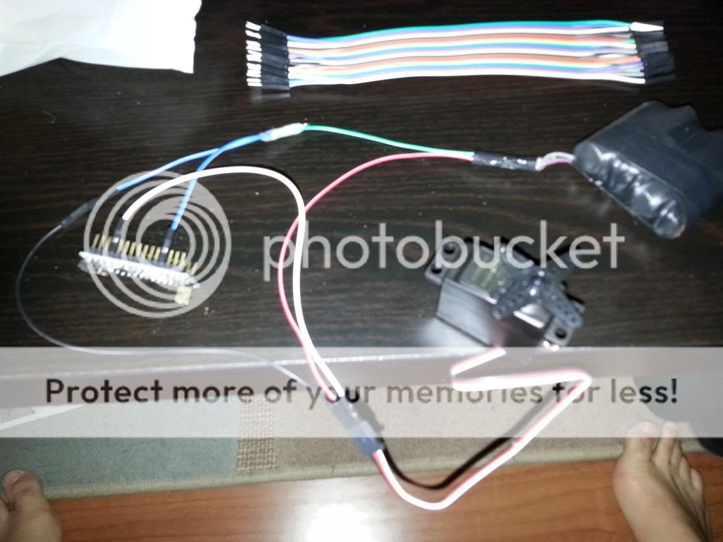
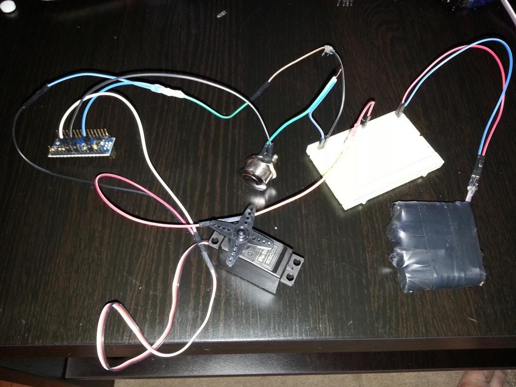
My external battery powered setup that can easily be hardwired and worked, so you can see what I did to test and learn everything and make sure I am running the arduino correctly.
Note: I just choose servo sweep in the file examples of the arduino app. Now I just need to get or make code to add a momentary switch aka the zwave relay switch or a doorbell button.
Pic explained: Controller = all white wires from motor goes to pin 9. Note: this took me a few hours to find out: with an external power source it requires a ground from the same battery = (green blue and black wires spliced together off of battery ground to"GND" pin on the same side as pin 9). Hook up 4 AA batteries in series = red wires are all positive in the pic coming from my battery packs purple wire. Make your own battery pack from batteries at home or get one of these from radio shack etc http://www.amazon.com/4AA-Battery-Holder-Wires-Switch/dp/B003YD8DQ8/ref=sr_1_2?ie=UTF8&qid=1385638573&sr=8-2&keywords=4aa+battery+pack
1.5vx4batteries=6 volts, or use a motorolla spn5334afor example and cut the end off to get pos and neg to get 5volts hardwired in) http://www.amazon.com/MOTOROLA-SPN5334A-CHARGER-XT865-Bionic/dp/B001IA0P6A don’t forget to buy two of the motorolla adapters so that you have one to run the arduino power when it’s not connected to your pc.
FYI - the futaba websites lists anything from 4.8 to 6v is needed.
4.8v = 47 oz/in so 47/16oz = 2.9 lbs per inch, or @ 6 volts = 57 oz/in = 3.5lbs/in = strong I think that logic is right.
copy paste this code into the screen that pops up in the adruino software, hit compile, the upload
Everything else the same in your circuit at this point
connect the white wire to pin D7 instead of D9
Connect another ground spliced off of your battery/power source to one of the button terminals. Add another ground wire on the other button terminal to the pin D5
That is the only change to your circuit besides the new code
Below is an example of a momentary button and the exact one I had lying around. auto stores have small red square buttons. Then move to a z wave relay which is the same thing but vera “pushes the button” or you can also push the button on the relay too.
I’m in the process of adding a detach / stop servo so that you could still use the strings to open and close the blinds as well. But this will get your circuit complete and ready for install with enough code to accomplish the basics.
I denoted the values to change if you want to change the angles of the blinds to open to. Look for any text after // which means that it’s just text on the rest of the line for people to read and label stuff
Note about gearing: Lets say the blinds are closed down to open them 90 degrees the pull string turns the “drive axel” 180 degrees so with a servo you have open and close. To close them shut upwards it’s another 180 degrees to complete a full rotation of the axel which the servo cannot do unless you jimmy rig it which I don’t need to do. SO… 180 deg on the code/servo = a 90 deg rotation of the blinds. half way open would be 90 = tilted down but open. Got it If not look at the axel as the strings or servo rotates it.
//zoomkat servo button toggle test 4-28-2012

#include <Servo.h>
int button = 5; //button pin, connect to ground to move servo
int press = 0;
Servo servo;
boolean toggle = true;

void setup()
{
  pinMode(button, INPUT); //arduino monitor pin state
  servo.attach(7); //pin for servo control signal
  digitalWrite(5, HIGH); //enable pullups to make pin high
}

void loop()
{
  press = digitalRead(button);
  if (press == LOW)
  {
    if(toggle)
    {
      servo.write(180);    //change this value to change the amount of turn
      toggle = !toggle;
    }
    else                         // the else statement that says go to 0 "close" if it's already at 180 "open"
    {
      servo.write(0);     //change this value for the value of the beginning of the servo's turn
      toggle = !toggle;
    }
  }
  delay(500);  //delay for debounce
}
Great info and glad to see your project coming along! Sorry I’m a little late to reply to your question, I’ve been out of town. I’ll copy and paste my basic code in below (prepare to be underwhelmed).
[code]#include <Servo.h>
const int button_pin = 2 ;
int led = 13;
Servo s1;
int pos = 0; // variable to store the servo position (0-135)
int button_value; //variable to store switch position
void setup()
{
s1.attach(9); // attaches the servo on pin 9
pinMode(led, OUTPUT);
}
void loop()
{
button_value = digitalRead(button_pin);
if (button_value==HIGH){
s1.write(135);
digitalWrite(led, HIGH); // turn the LED on
}
else {
s1.write(45);
digitalWrite(led, LOW); // turn the LED off
}
}[/code]
I used some hardwood I had lying around to make the mount. I ended up getting the Lowes 2 1/2" faux blinds bc Home depot’s brand did not have extra axle exposed. Lowes had about 2" that could slide to either side through the gear and string rollers.
I used a 1/8 sheet of plexiglass lying around and cut a small piece out amd made a circle, drilled a hole a little smaller than the blind’s fiberglass axle put an old soldering iron with a tip ground down to roughly the correct diameter in the middle and melted the plastic once melted I pushed it onto the axle. voila
Don’t be too disappointed from what I’m about to tell you people researching. I have a 52" wide window which probably requires a lot of torque to move the couple extra string rollers. I ran into an issue, the servo is underpowered by probably 25% since it can open a bit and stalls. I’m ordering the Futaba S3305. Maybe a beefy one too, I have clearance above the blinds so my goal is to find a servo with a drive shaft that will fit in the 1 7/8 to 2 2/8" wide frame while the rest sticks out of the top. My wife bought a valance today for the top part of the blinds so that will hide the motor easily.
My servo goal max is a 2" deep with drive on this face x 4" high x 3.5" wide. Let me know if you guys know servos well. I’ll try it out and report.
Thoughts about servos given my situation which you could eventually recreate, Pics soon too:
With the lowes 2 1/2" faux blinds with the servo motor on the right side you have unlimited height unless you have them mounted inside the window which again is up to you given a valance etc, but it is 2 3/16 deep with a ribbed top edge narrowing the top of the channel to 1 7/8" but it could be bent etc if need be and 3.5 wide (again, if mounted outside the window it is unlimited and can be covered by the valance as well). I am mount in the window and have an arch so I’m limited by about 4" of height atm.
UPDATE 12/5
The newer servo seems a bit underpowered but works. I’m thinking that bc the gear from the axel to the turn rode/strings that the OP was taken out the friction fro that 90 deg turn of gearing would be good for me. The next option would be to take out the heavy 1/2" board at the bottom that does not really seem to do much. Third which is my goal tonight find a stronger servo.
Remember how I said that with the lowe’s 2 1/2" faux blinds the axel slides back and forth. Well I slid the axel out of that 90 degree gearing box that runs the strings to open and close the blinds. Now the blinds open great! I can even tug on them a bit maybe 5 lbs while they are opening and it still works. I will say that even with the strings and this large of a window it was hard to pull them the extra 10% so that they go completely closed flat against each other and and tuck up; this servo cannot do that as well. I’m going to try and set it at 10 deg and 180 which geared = 10 and 90 deg to get rid of the servo motor flutter when trying to close all the way.
The double power supply (one to motor & one to arduino) works great with that extra strong motor!
;D This is what I need ;D
For $30ish This appears to be 480 oz/in at 6 volts. If I really need them to close all the way for the projector I may get this one. I’m going to see how it looks in the light tomorrow.
I haven’t been able to spend more time on the programming side, but could you use the detach servo command in the Arduino code to get rid of the flutter you’re experiencing, as well?
Also, I noticed in your video that you haven’t hooked up the relay yet. Just want to give you a heads up that those screws strip really easily and to not over torque them.
If I close them completely with my fingers and the motor detached from the axle then the blinds sightly open a little. I think if you detach power from it then the motor may not have enough friction to keep the blinds closed and they will slightly open back up. The string/ 90deg gear seems to hold it closed all the way some how, they kind of pull up as they lay flat against each other. I would recommend sticking with the 2" blinds for this weight/friction issue unless a stepper motor locks at each step like an electric hoist.
Okay so I have everything hard wired and working with the analog momentary switch no issues. I connected the same 2 wires to the z wave relay and when I hit the on button I get the blinds in a rolling open and close (pulsing type signal) until I turn them off. Just wondering why the z wave button would be doing that. I have no solid ideas, maybe change the milliseconds the signal is sent. I have the same wires from the momentary switch going to the isolated relay pins of the zwave relay and relay has separate power to the full-time AC pins. Wierd there is no ground to the z wave device. o-well
ms as in delay between signal sent, I think I saw something about that in the garage door relay section, but the device is receiving the signal just weird output. It works fine when connecting the wires and it’s isolated to the relay.
The ohm meter jumps around as the connection is made. On voltage dc it shows 1,2,3,4,5 then 1,2,3,4,5 looping. Wierd???. All I have done is connect it to the network with no adjustments in the device settings. The scenario happens via z wave or the relay button press.
Ah ha… Now that I think about it I have the code set for a momentary use using that button, and the code is not set for on/off just “on for a split second” = open to 180 degrees if at 180 close to 12 degrees
we are headed out tonight, but maybe I’ll try your code tomorrow, or figure out how to end the signal after a few ms like my garage door. Oh,but I think the garage door plugin that creates that off signal would not be running if I pressed the button manually so I have to follow your code using “on/off” vs just a quick “on” signal.
Well I was a bit confused and I added my assumptions on the lines of code I was trying to figure out comparing it to the code I first had. White control line was 9. In the other code the same ground from the servo had to go to the arduino as well then looped through the z wave and back to another pin on the arduino. I assume you still need 5 lines. lines 1 and 2 = vin/12v & ground for arduino’s seperate power; 3.)then control, 4.) ground and same ground spliced to z wave, and 5.) that z wave ground relayed back to arduino.
Thanks for all your help reallifeonhold. This is the home stretch, just to get zwave running. Friends love it. I’ll send them to you if they want to buy a kit, you can add them to the waiting list until you get enough people/windows. I only have 2 normal windows and everything else is vertical sliders so I’m in for a couple vertical kits when you make them Send me your donate paypal link and I’ll send you some beer money for all the help.
[code]#include <Servo.h>
const int button_pin = 2 ; // assuming this is ground from the same power as the servo and the relay
int led = 13; // assuming this is the zwave line back in
Servo s1;
int pos = 0; // variable to store the servo position (0-135) //if this is 0 where is 180 code or is it just full limit of the servo
int button_value; //variable to store switch position //do I need to add 180 here? or this is the auto full open full close?
void setup()
{
s1.attach(9); // attaches the servo’s control wire on pin 9 White wire
pinMode(led, OUTPUT);
}
//is the rest of this code below just LED or button position with the 135 and 45?
void loop()
{
button_value = digitalRead(button_pin);
if (button_value==HIGH){
s1.write(135);
digitalWrite(led, HIGH); // turn the LED on
}
else {
s1.write(45);
digitalWrite(led, LOW); // turn the LED off
}
}[/code]
I’m going to split up my replies in hopes of clarifying things…we’ll start with the code:
#include <Servo.h>
const int button_pin = 2 ; // assuming this is ground from the same power as the servo and the relay
→ when the relay trips, it should send 5V to D2
int led = 13; // assuming this is the zwave line back in
→ Pin 13 is the built in LED on the Arduino. I just used this as a visual confirmation as to which state the Arduino was in.
Servo s1;
int pos = 0; // variable to store the servo position (0-135) //if this is 0 where is 180 code or is it just full limit of the servo
–>I found that I only needed 90 degrees of movement and that corresponded to positions 45-135 on the servo.
int button_value; //variable to store switch position //do I need to add 180 here? or this is the auto full open full close?
→ If you need 180 degrees worth of movement, this is where you’d change the numbers to 0-180
void setup()
{
s1.attach(9); // attaches the servo’s control wire on pin 9 White wire
→ Correct, this tells the Arduino to output the servo commands on pin 9.
pinMode(led, OUTPUT);
}
//is the rest of this code below just LED or button position with the 135 and 45?
→ This is the main code that tells the servo to move to the position at 45 degrees or 135 degrees (the s1.write() commands) depending on whether the switch is open or closed. Based on which position it’s in it will either light the LED or not.
void loop()
{
button_value = digitalRead(button_pin);
if (button_value==HIGH){
s1.write(135);
digitalWrite(led, HIGH); // turn the LED on
}
else {
s1.write(45);
digitalWrite(led, LOW); // turn the LED off
}
}
Based on your code, it looks like you’re using Pin 5 for your input from the switch (my program uses Pin 2) and Pin 7 to control the servo (Pin 9 in my program).
The fluctuating voltage that you’re seeing is very strange. Is there a chance you’re using one of the analog pins instead of the digital ones?
Hi all
Im new to here and to all this automation stuff so still learning just wondering is there a way to make this type of thing start and stop tilt n stop just so its not like up or down and open or closed hope this makes sense. Thank u in advance
So can someone make a complete parts list of what would be needed?
Or can someone direct us whom to contact to purchase 3 of these units for my blinds 8)
We cannot all PM you because to new to the forum. But very interested in a couple of these units.