For the setup I put together, the parts list would be as follows:
(1) set of 2" blinds. Seems like 3’-4’ wide is about limit as to what the servo can manage.
(1) Futaba S3305 (I used a 3003, but this servo has much higher torque values and should work a little better)
(1) Remotec ZFM-80 Z-wave relay
(1) Arduino Nano v. 3.0 or equiv.
(1) Servo mount. I couldn’t find an off-the-shelf solution for this, so I made my own. When I get a chance, I can measure the exact dimensions of the piece (the one included in earlier in the thread needed a little bit of tweaking to get everything to line up exactly).
Misc. hookup wires and a means of getting power to the relay (120VAC).
Code for the Arduino: http://forum.micasaverde.com/index.php/topic,17118.msg138472.html#msg138472
*This code is super basic and could probably stand to be improved. Two changes I would make is to slow the opening/closing speed of the blinds and to put in code to disconnect the servo once it reaches the open or closed position.
Partswise, I think that should cover the basics of what you’ll need to duplicate my setup.
Question I have, is there a way to do this and still keep the function of pulling on the string? I know the servos usually lock in place, but for manual operation, instead of installing a button near the windows, I would like to still be able to just use the string to open and close. Could a regular motor be used (assuming if yes, it wouldn’t be as accurate as a servo or stepper).
With my solution A Stepper motor, you cannot override the motor. You must do it with the zwave control with my solution.
I just need to attach to board and run 5 volt to motor and Arduino Nano. Then run 110 to the Remotec ZFM-80. It is great what you can do with about 60 bucks. The biggest cost is the Remotec. Stepper, Arduino Nano, & wires under 16 bucks.
You can still use the strings attached if you find a little bit stronger motor. Maybe double what I last used. I could open the shades quite a bit with the strings attached and all the way when not attached. Again, my window is large so smaller windows won’t need a larger motor.
Checking in after a bit to see if anyone has made any improvements. I’m back in school working on another degree so I have been way too busy. The only issue I have now is creating the code to run the motor. I think I’ll just use the manual switch from the video for now.
Not sure if I mentioned it before. The issue is that the zwave relay is either on or off continuous power vs the manual button from my video is momentary on then right back to off when you release the button.
So we need a way to turn the power on to rotate the motor then when the power is off (relay off) the adruino powered separately then knows to turn the motor back closed
Or
set it up like the garage door app. sends a signal (z wave momentary pulse) that trips the adruino (like a garage door remote button) to turn a direction. Next signal turns opposite direction just like the manual momentary button.
I don’t have time to learn the code for the arduino right now. so I may just use the garage door app if I get a little time to set things up. So if anyone else gets anywhere, let us all know, then we can finalize a working system, find better parts etc. then maybe someone can CNC some acrylic or aluminum parts and sell them.
On the vertical blinds idea, if you had the slide open/ close by string option then you could use a stepper motor to pull the strings like an add-a-motor. Then just use the motor like the video to close and open the slats. An app would have to first open the slats then the second motor would slide the blinds back out of the way.
[quote=“reallifeonhold, post:41, topic:177421”]For the setup I put together, the parts list would be as follows:
(1) 22k resistor
Partswise, I think that should cover the basics of what you’ll need to duplicate my setup.[/quote]
You can eliminate the pull-down resistor by activating the internal pull-up resistor of the arduino with this:
digitalWrite(button_pin,HIGH);
Then reverse your logic to match. So your sketch would look like this:
#include <Servo.h>

const int button_pin = 2 ;
int led = 13;

Servo s1;
int pos = 0; // variable to store the servo position (0-135)
int button_value; //variable to store switch position

void setup()
{
  s1.attach(9); // attaches the servo on pin 9
  pinMode(led, OUTPUT);

  // Turn On internal Pull-up resistor
  // No resistor needed. Connect to one pin on button.
  // Connect other pin on button to ground
  digitalWrite(button_pin,HIGH);
}

void loop()
{
  button_value = digitalRead(button_pin);
  // reversed logic for pull-up resistor instead of pull-down
  if (button_value==LOW){
    s1.write(135);
    digitalWrite(led, HIGH);   // turn the LED on
    }
  else {
    s1.write(45);
   digitalWrite(led, LOW);    // turn the LED off
    }
}
Thanks for all your hard work. I have used what you done with great success. My question is can the Aeotec micro smart switch be substituted for the ZFM-80 Z Wave dry contact? The ZFM seams to be out of stock.
I haven’t looked into that one, but the Evolve LFM-20 is the same thing but without a button or face plate and would rely solely on z wave control, where as the original relay has a button on the front and can be mounted as a manual switch for visiting family etc. It may even work without z wave if you ever sell and move out. The LFM-20 is what I am using to simulate a button press on my garage door for z wave garage door. You are just looking for a separated relay switch e.g. couple wires power the device, one wire pos or ned goes in and the same pos or neg goes back out when you press the button or hit z wave to complete the circuit. Nothing voltage wize is added or taken away it’s just an isolated switch.
Hi,
Can you please share the circuit diagram between Servo, Z wave relay and Arduino nano.
thank you in advance. and I am going through the code and if you can give me clean code, will try to experiment.
thank you
mahe
Hi. Looks like all of the pics got wiped out. Unfortunately, I looked through my files and I couldn’t find anything related to this project other than what’s in this thread. I ended up switching my setup over to the system laid out at https://www.mysensors.org/ a couple of years ago and it’s worked out very well. I’d recommend going that route as it will give you more control and flexibility.
Thank you for the quick response, and in any way can you help me in rough drawing on connecting the devices. that way I can start with it, once i have that wiring understanding , I can do my coding
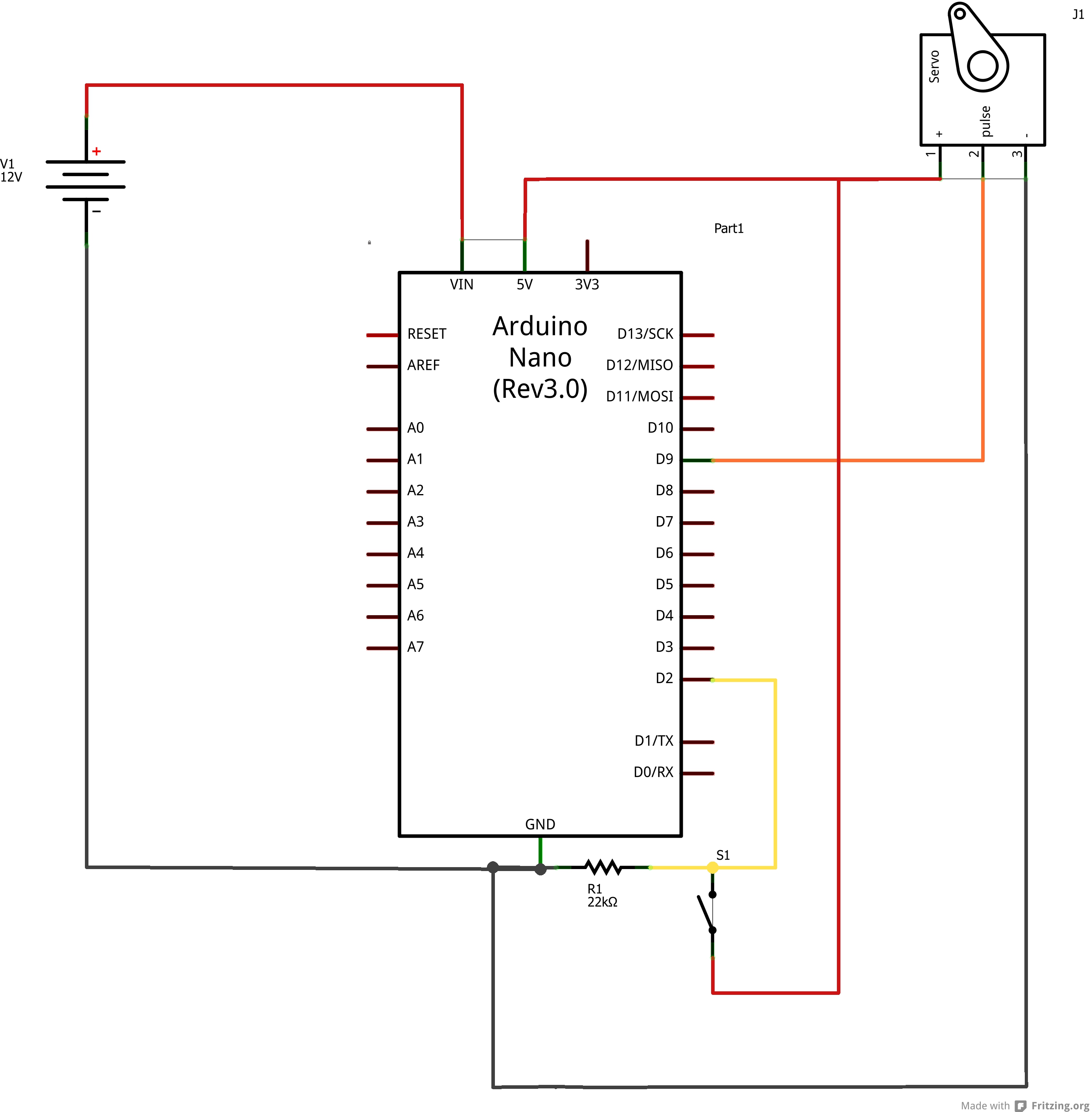
This should be the circuit that was used at the time. S1 represents the Z-Wave switch/relay. (that 5V line running to the switch should not intersect with the D9 <–> Servo wire)
As mentioned above, with some modifications to the code, you can eliminate the external resistor.
Thank you once again, it worked, and when it goes to High, the servo is powered and trying to cut the power when it reaches high and when relay on /off got to low.