After searching and reading both the WIKI and forum I am confused on how to implement a simple SPST switch on a 53v line or a 220v line. Any feedback on which products would work for either of the applications would be appreciated.
A SPST is usually used when switching power in a single phase circuit, usually when using voltages up to 120v AC (one live wire, one neutral and a ground). 220 volts has two live wires (110 volts each when measured to the neutral) and a ground, the neutral is not used. This requires a DPDT switch. Examples of this would be some hot water tanks, some pool pumps, most base board heaters almost anything labeled 220v.
If you try using a SPST switch with 220v it will only cut the power to one half the circuit leaving one live wire. If you do this make sure your life insurance is paid in full before applying the power.
Thanks … should of just said an on/off switch in each environment ![]()
Well, that depends… where do you live? If I’m not mistaken, the above applies in the US, but I believe in other countries, you get 220v from phase to neutral. If that’s the case, are you using US z-wave or EU zwave? I don’t know about EU z-wave, but the US z-wave scenarios are as follows:
220V, 1p breaker (outside of US), but using US z-wave, I think the zrf113 or zrw113 contact wires are rated up to 277V, but you still need 120V to power the z-wave radio.
220V, 2p breaker (in US), using US z-wave, you would actually need a DPST switch… double pole (one for each “phase”), single throw (one conducting, or “On” position). What you could do in this scenario is use a standard z-wave switch controlling a 2-pole contactor or relay that has 120V control voltage wired to the z-wave switch, and pole contacts rated at 120v.
What are you trying to control that is 53V? You can use a zrf113 or zrw113 for this, as long as you have 120v power available to power the z-wave radio.
EDIT: The zrf113 and zrw113 are rated to 277v, but only 20A, so my guess is if you are in the US, you’re probalby looking at a 30+ amp, 2pole circuit, so a contractor would likely be your best bet. What are you trying to control?
Woodsby … sorry for the lack of detail … the 220v circuit is for my well pump and the 53v is the control line from a watermaker to a boiler. I wish to be able to turn them off when my cabin is unoccupied. Looks like I might have to use a relay/contactor on each with a common z-wave switch.
Sounds like you need a 4-pole contactor. What size breaker do you have feeding your well pump - what ampacity?
Woodsby … the pump breaker is 30Amp.
I would get a 4-pole 30A lighting contactor with 120V coil - I think I found on ebay the other day for less than $100. I would make sure to get an enclosure suited for your application - NEMA1 for indoor or NEMA3R or better for outdoor or where subject to water. Also, make sure that all your wiring in the enclosure is 600V building wire, even on the 53V circuit, to satisfy code.
Buy any z-wave (binary) switch, and wire the switch leg and the return (neutral) wire to the coil contacts on the contactor, and wire your 2 hot conductors for the well pump and the conductor for your boiler through three poles of the contactor, and you’re done.
Au Contraire!
MANY 220V Air Conditioners USE SPST contactors. There is a reason for this. But I am not sure why it is. But again MANY 220V air conditioners USE SPST Contactors. IE: one of the input power terminals is shorted to the power out feed terminal.
Click on the following link to see a picture of one these SPST, Double Pole contactors
Picture of a SPST 220V contactor - Google Search.
I have been trying (but no luck yet) to find “WHY” they use this SPST contactor on a 220V Air Conditioner on MANY modern air conditioners. Check it out.
The following is a Diagram on my AC using this type of contactor. WHY?
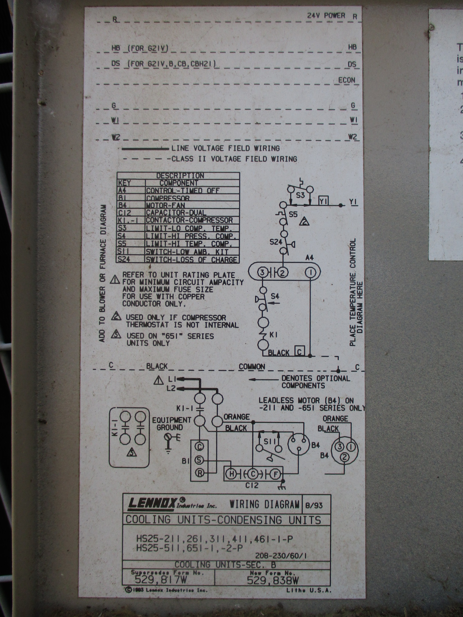
In a single-phase system like this, you only need to switch one leg to control the compressor. If the contact actually is two-pole as installed (i.e. as-drawn == as-built), I can think of two reasons. One is that they may be using L2 as part of a crankcase heater circuit (not shown on the diagram, but can be added at the factory or in the field based on need/order), so that leg needs to be unswitched/always on. The other is that it makes for a quick repair in the field: when the one pole’s contacts burn up from arcing, and they will, the field “tech” can just switch the connections to the unused pole of the same contactor to get the unit back up and running–a 60-second repair and no replacement needed.