I’m going to split up my replies in hopes of clarifying things…we’ll start with the code:
#include <Servo.h>
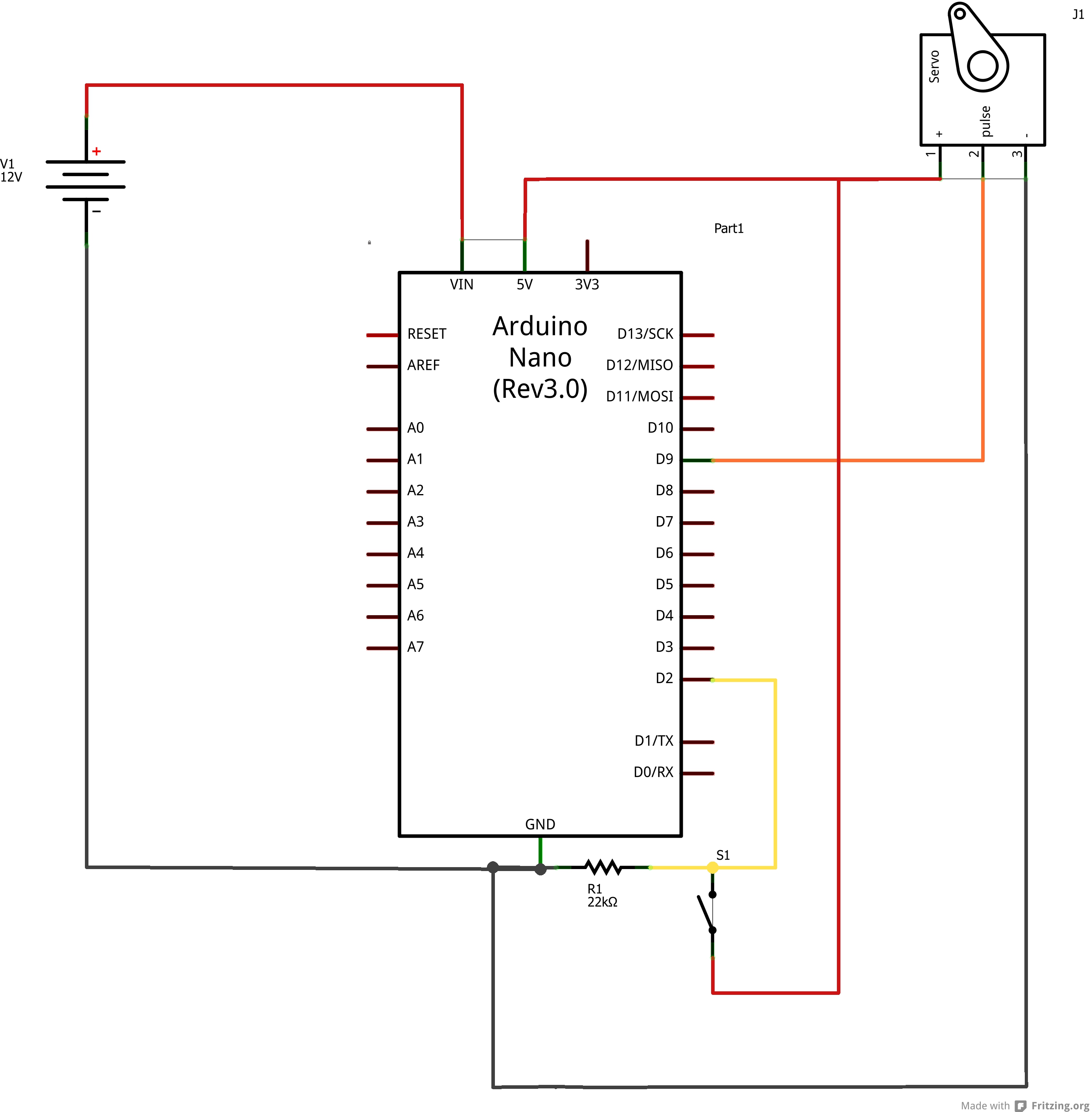
const int button_pin = 2 ; // assuming this is ground from the same power as the servo and the relay
→ when the relay trips, it should send 5V to D2
int led = 13; // assuming this is the zwave line back in
→ Pin 13 is the built in LED on the Arduino. I just used this as a visual confirmation as to which state the Arduino was in.
Servo s1;
int pos = 0; // variable to store the servo position (0-135) //if this is 0 where is 180 code or is it just full limit of the servo
–>I found that I only needed 90 degrees of movement and that corresponded to positions 45-135 on the servo.
int button_value; //variable to store switch position //do I need to add 180 here? or this is the auto full open full close?
→ If you need 180 degrees worth of movement, this is where you’d change the numbers to 0-180
void setup()
{
s1.attach(9); // attaches the servo’s control wire on pin 9 White wire ![]()
→ Correct, this tells the Arduino to output the servo commands on pin 9.
pinMode(led, OUTPUT);
}
//is the rest of this code below just LED or button position with the 135 and 45?
→ This is the main code that tells the servo to move to the position at 45 degrees or 135 degrees (the s1.write() commands) depending on whether the switch is open or closed. Based on which position it’s in it will either light the LED or not.
void loop()
{
button_value = digitalRead(button_pin);
if (button_value==HIGH){
s1.write(135);
digitalWrite(led, HIGH); // turn the LED on
}
else {
s1.write(45);
digitalWrite(led, LOW); // turn the LED off
}
}