G’day all,
I have seen a few posts on the forum regarding integrating a Zwave two way switch (Enerwave ZWN-RSM2-Plus) with a hood fan. I am a little confused regarding a few of the wires and any help would be appreciated.
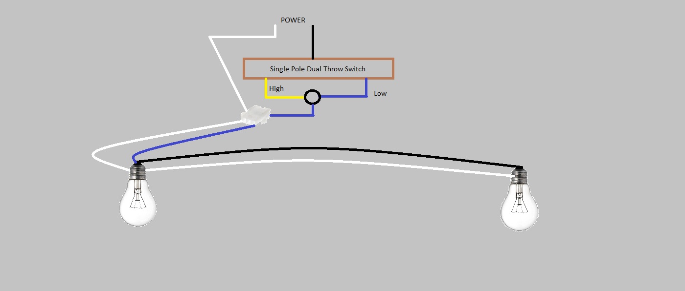
My current range hood has a light switch that has three settings Low/Off/High and is currentl wired as shown below.
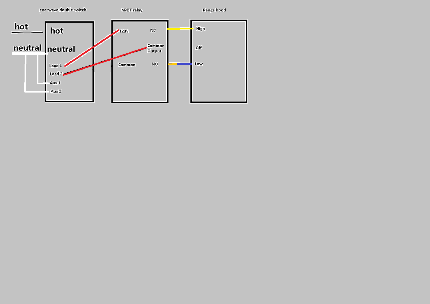
I would like to use the Enerwave switched mentioned above to control the lights and add a single pole relay to avoid the potential for a short. A previous forum post on Smarthings discussed this same issue ([Kitchen hood fan control (Low/Hi/Off)? - #11 by Alan_Coe - Devices & Integrations - SmartThings Community] however I did not understand the answer to question #1 in the thread. I have included a diagram of my understanding of what the correct wiring should but could someone please confirm this is correct.
What you have looks correct.
load 1 turns on power goes through low speed, turn on load 2 and power goes to high speed, turn off loads 1/2 power turns off.
Just to add this zwave unit would remove the need for the relay and has built in interlocking
Awesome, thanks much! The only draw back to the Zooz multi relay is the requirement for a plug in power supply that would be a tight squeeze in the range hood.
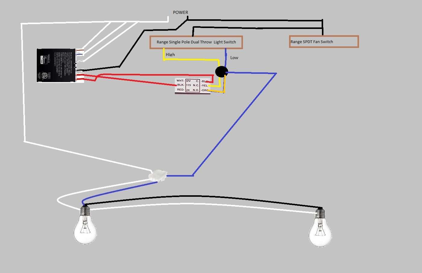
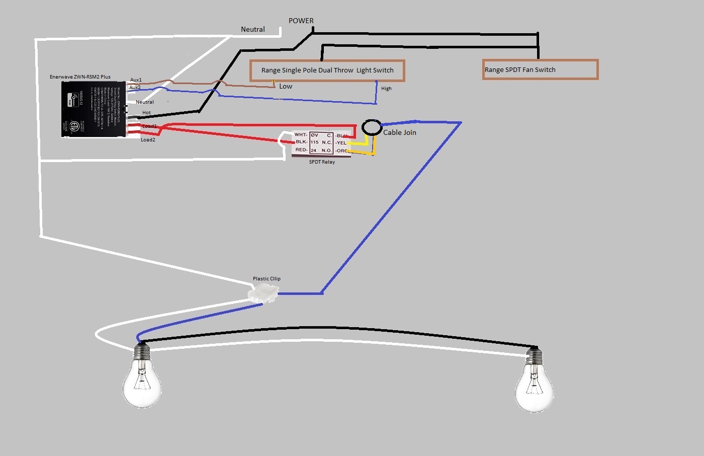
One final thing to make sure I don’t screw this up but here the exact wiring diagram as I see it (the black circle would be the wires marretted together).
All good,
The hood fan is a Nutone Allure model, the first drawing in this thread shows the current wiring minus the fan switch jumper to power the light switch.
I’m just switching the lighting portion but the power for the light switch is from a jumper on the Fan switch.
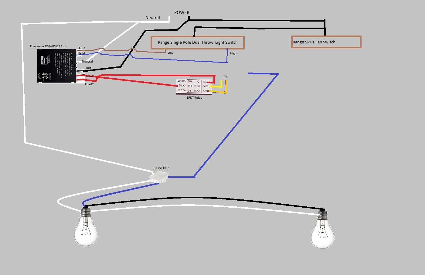
The Enerwave relay wires from top to bottom are as follow:
Aux1
Aux2
Neutral
Hot/Power
Load1
Load2
Neutral and Power at the top of the diagram are where the 14-2 power cable comes in. The hot wire goes to the range fan switch and has a jumper to bring power over to the light switch.
Yes the lights have a low setting which is dimmer than the high setting. the brown squares represent the physical switches on the range hood (note I left out the fan high and low wires as i’m not automating it).
In the first diagram I posted representing the current layout the circle represents the three wires heat wrapped together (low,high and lead to the light).
As there is a difference in light levels i will guess that the black circle is some sort of dimming switching device, that dims light depending if power is on low or high wire.
Everthing in diagram is correct just need to move original high and low
so put
low wire on n/c
high wire on n/o
Also just confirm that the output from original light switch is mains voltage, i.e the voltage from high is the same as the voltage from low. As the switch might do the dimming, and black circle may just be a cable joint.