https://www.uk-automation.co.uk/z-wave-shock-and-vibration-sensor/ but its pretty much double the price
I ordered an Aqara mini switch https://www.gearbest.com/smart-home-controls/pp_009395405312.html?wid=1349303
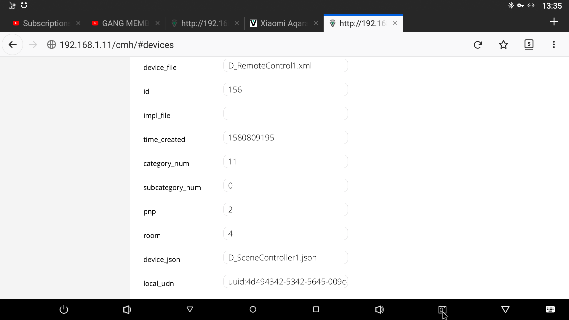
I managed to include device, which showed as a genericIO device.
I have messed with the device type and files.
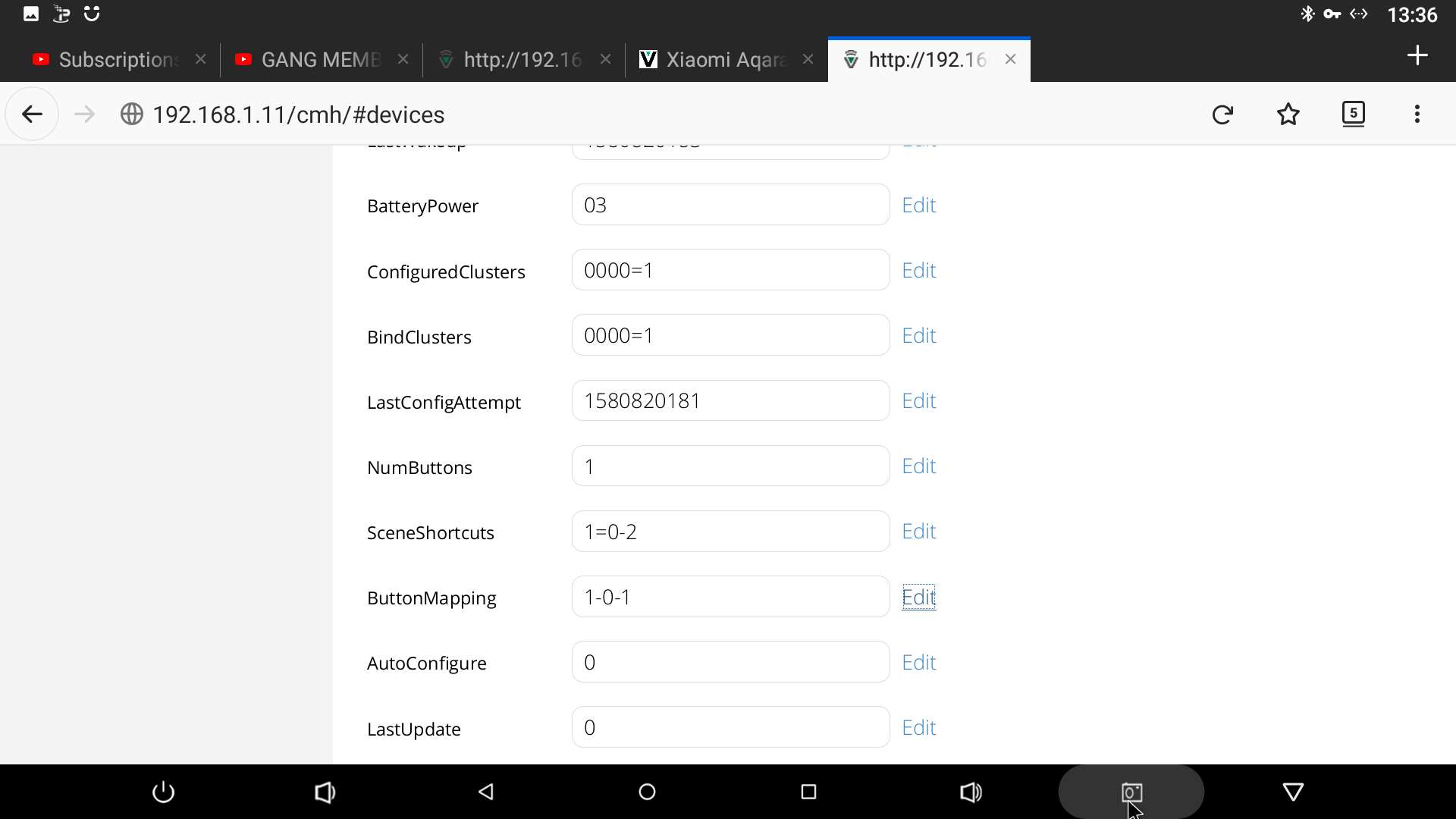
Also added ButtonMapping variable.
I have not managed to get this device to work.
Has anyone have any ideas what i should try?
you would have to find out ultimately what it does, is it a scene controller, is it a momentary switch, looks like a scene controller with one button. so vera has no device file for a one button scene controller so you would have to create one. u possibly you could use the last update field to trigger stuff
Sadly LastUpdate does not update.
Yes its a scene controller or maybe a remote. when it first configured and i set it to D_SceneController, it asked how many buttons, I inputed 1 and then it asked me to select a scene.
When adding the temp/humdidity sensor, i got no temp or humidity value till i added the cluster 0402/0405. Now im i have seached and tried different cluster values but none seem to work. SO i was wondering if anyone has any suggestions for cluster values for zigbee scene contollers/remotes etc?
yeah i am here reasearching clusters i have a zigbeeMqtt stick i need to set up so i can do some scanning but the problem it the cluster mappings
1.1.1 General
The General clusters implemented by NXP are listed and outlined in the table below.
These clusters are detailed in ‘Part III: General Clusters’ of this manual.
| Cluster | Cluster ID | Description |
|---|---|---|
| Basic | 0x0000 | The Basic cluster contains the basic properties of a |
| ZigBee device (e.g. software and hardware versions) | ||
| and allows the setting of user-defined properties (such | ||
| as location). This cluster is detailed in Chapter 8. | ||
| Power Configuration | 0x0001 | The Power Configuration cluster allows the details of a |
| device’s power source(s) to be determined and under/ | ||
| over-voltage alarms to be configured. This cluster is | ||
| detailed in Chapter 9. | ||
| Device Temperature Configuration | 0x0002 | The Device Temperature Configuration cluster allows |
| information about the internal temperature of a device | ||
| to be obtained and under/over-temperature alarms to | ||
| be configured. This cluster is detailed in Chapter 10. | ||
| Identify | 0x0003 | The Identify cluster allows a ZigBee device to make |
| itself known visually (e.g. by flashing a light) to an | ||
| observer, such as a network installer. This cluster is | ||
| detailed in Chapter 11. | ||
| Groups | 0x0004 | The Groups cluster allows the management of the |
| Group table concerned with group addressing - that is, | ||
| the targeting of multiple endpoints using a single | ||
| address. This cluster is detailed in Chapter 12. | ||
| Scenes | 0x0005 | The Scenes cluster allows the management of pre- |
| defined sets of cluster attribute values called scenes, | ||
| where a scene can be stored, retrieved and applied to | ||
| put the system into a pre-determined state. This clus- | ||
| ter is detailed in Chapter 13. | ||
| On/Off | 0x0006 | The On/Off cluster allows a device to be put into the |
| ‘on’ and ‘off’ states, or toggled between the two states. | ||
| This cluster is detailed in Chapter 14. | ||
| On/Off Switch Configuration | 0x0007 | The On/Off Switch Configuration cluster allows the |
| switch type on a device to be defined, as well as the | ||
| commands to be generated when the switch is moved | ||
| between its two states. This cluster is detailed in | ||
| Chapter 15. | ||
| Level Control | 0x0008 | The Level Control cluster allows control of the level of |
| a physical quantity (e.g. heat output) on a device. This | ||
| cluster is detailed in Chapter 16. | ||
| Alarms | 0x0009 | The Alarms cluster is used for sending alarm notifica- |
| tions and the general configuration of alarms for all | ||
| other clusters on the ZigBee device (individual alarm | ||
| conditions are set in the corresponding clusters). Thi s | ||
| cluster is detailed in Chapter 17. | ||
| Cluster | Cluster ID | Description |
| Time | 0x000A | The Time cluster provides an interface to a real-time |
| clock on a ZigBee device, allowing the clock time to be | ||
| read and written in order to synchronise the clock to a | ||
| time standard - the number of seconds since 0 hrs 0 | ||
| mins 0 secs on 1st January 2000 UTC (Co-ordinated | ||
| Universal Time). This cluster includes functionality for | ||
| local time-zone and daylight saving time. This cluster | ||
| is detailed in Chapter 18. | ||
| Analogue Input (Basic) | 0x000C | The Analogue Input (Basic) cluster provides an inter- |
| face for accessing an analogue measurement. This | ||
| cluster is detailed in Section 19.1. | ||
| Analogue Output (Basic) | 0x000D | The Analogue Output (Basic) cluster provides an |
| interface for setting the value of an analogue output. | ||
| This cluster is detailed in Section 19.2. | ||
| Binary Input (Basic) | 0x000F | The Binary Input (Basic) cluster provides an interface |
| for accessing a binary (two-state) measurement. This | ||
| cluster is detailed in Section 19.3. | ||
| Binary Output (Basic) | 0x0010 | The Binary Output (Basic) cluster provides an inter- |
| face for setting the state of a binary (two-state) output. | ||
| This cluster is detailed in Section 19.4. | ||
| Multistate Input (Basic) | 0x0012 | The Multistate Input (Basic) cluster provides an inter- |
| face for accessing a multistate measurement (that can | ||
| take one of a set of fixed states). This cluster is | ||
| detailed in Section 19.5. | ||
| Multistate Output (Basic) | 0x0013 | The Multistate Output (Basic) cluster provides an |
| interface for setting the value of a multistate output | ||
| (that can take one of a set of fixed states). This cluster | ||
| is detailed in Section 19.6. | ||
| Poll Control | 0x0020 | The Poll Control cluster provides an interface for |
| remotely controlling the rate at which a ZigBee End | ||
| Device polls its parent for data. This cluster is detailed | ||
| in Chapter 20. | ||
| Power Profile | 0x001A | The Power Profile cluster provides an interface |
| between a home appliance (e.g. a washing machine) | ||
| and the controller of an energy management system. | ||
| This cluster is detailed in Chapter 21. | ||
| Diagnostics | 0x0B05 | The Diagnostics cluster allows the operation of the |
| ZigBee PRO stack to be followed over time. This clus- | ||
| ter is detailed in Chapter 22. | ||
1.1.2 Measurement and Sensing
The Measurement and Sensing clusters implemented by NXP are listed and outlined in the table below. These clusters are detailed in ‘Part IV: Measurement and Sensing Clusters’ of this manual.
| Cluster | Cluster ID | Description |
|---|---|---|
| Illuminance Measurement | 0x0400 | The Illuminance Measurement cluster provides an |
| interface to an illuminance measuring device, allowing | ||
| the configuration of measuring and the reporting of | ||
| measurements. This cluster is detailed in Chapter 23. | ||
| Illuminance Level Sensing | 0x0401 | The Illuminance Level Sensing cluster provides an |
| interface to light-level sensing functionality. This clus- | ||
| ter is detailed in Chapter 24. | ||
| Temperature Measurement | 0x0402 | The Temperature Measurement cluster provides an |
| interface to a temperature measuring device, allowing | ||
| the configuration of measuring and the reporting of | ||
| measurements. This cluster is detailed in Chapter 25. | ||
| Pressure Measurement | 0x0403 | The Pressure Measurement cluster provides an inter- |
| face to a pressure measuring device, allowing the | ||
| configuration of measuring and the reporting of meas- | ||
| urements. This cluster is detailed in Chapter 26. | ||
| Flow Measurement | 0x0404 | The Flow Measurement cluster provides an interface |
| to a flow measuring device for a fluid, allowing the | ||
| configuration of measuring and the reporting of meas- | ||
| urements. This cluster is detailed in Chapter 27. | ||
| Relative Humidity Measurement | 0x0405 | The Relative Humidity Measurement cluster provides |
| an interface to a humidity measuring device, allowing | ||
| the configuration of relative humidity measuring and | ||
| the reporting of measurements. This cluster is detailed | ||
| in Chapter 28. | ||
| Occupancy Sensing | 0x0406 | The Occupancy Sensing cluster provides an interface |
| to an occupancy sensor, allowing the configuration of | ||
| sensing and the reporting of status. This cluster is | ||
| detailed in Chapter 29. | ||
| Electrical Measurement | 0x0B04 | The Electrical Measurement cluster provides an inter- |
| face for obtaining electrical measurements from a | ||
| device. This cluster is detailed in Chapter 30. | ||
1.1.3 Lighting
The Lighting clusters implemented by NXP are listed and outlined in the table below.
These clusters are detailed in ‘Part V: Lighting Clusters’ of this manual.
| Cluster | Cluster ID | Description |
|---|---|---|
| Colour Control | 0x0300 | The Colour Control cluster can be used to adjust the |
| colour of a light (it does not govern the overall lumi- | ||
| nance of the light, as this is controlled using the Level | ||
| Control cluster). This cluster is detailed in Chapter 31. | ||
| Ballast Configuration | 0x0301 | The Ballast Configuration cluster can be used to con- |
| figure a lighting ballast that restricts the light levels of | ||
| a connected set of lamps. This cluster is detailed in | ||
| Chapter 32. | ||
1.1.4 Heating, Ventilation and Air-Conditioning (HVAC)
The HVAC clusters implemented by NXP are listed and outlined in the table below.
These clusters are detailed in ‘Part VI: HVAC Clusters’ of this manual.
| Cluster | Cluster ID | Description |
|---|---|---|
| Thermostat | 0x0201 | The Thermostat cluster provides a means of configur- |
| ing and controlling the functionality of a thermostat. | ||
| This cluster is detailed in Chapter 33. | ||
| Fan Control | 0x0202 | The Fan Control cluster provides a means of con- |
| trolling the speed or state of a fan which may be part | ||
| of a heating or cooling system. The cluster is detailed | ||
| in Chapter 34. | ||
| Thermostat User Interface Configuration | 0x0204 | The Thermostat User Interface (UI) Configuration |
| cluster provides a means of configuring the user inter- | ||
| face (keypad and/or LCD screen) for a thermostat or a | ||
| thermostat controller device. This cluster is detailed in | ||
| Chapter 35. | ||
1.1.5 Closures
The Closure clusters implemented by NXP are listed and outlined in the table below.
These clusters are detailed in ‘Part VII: Closure Clusters’ of this manual.
| Cluster | Cluster ID | Description |
|---|---|---|
| Door Lock | 0x0101 | The Door Lock cluster provides a means of represent- |
| ing the state of a door lock and (optionally) the door. | ||
| This cluster is detailed in Chapter 36. | ||
1.1.6 Security and Safety
The Security and Safety clusters implemented by NXP are listed and outlined in the table below. These clusters are detailed in ‘Part VIII: Security and Safety Clusters’ of this manual.
| Cluster | Cluster ID | Description |
|---|---|---|
| IAS Zone | 0x0500 | The IAS Zone cluster provides an interface to a zone |
| device in an IAS (Intruder Alarm System). This cluster | ||
| is detailed in Chapter 37. | ||
| IAS ACE (Ancillary Control Equipment) | 0x0501 | The IAS ACE cluster provides a control interface to a |
| CIE (Control and Indicating Equipment) device in an | ||
| IAS (Intruder Alarm System). This cluster is detailed in | ||
| Chapter 38. | ||
| IAS WD (Warning Device) | 0x0502 | The IAS WD cluster provides an interface to a Warn- |
| ing Device in an IAS (Intruder Alarm System). For | ||
| example, a CIE (Control and Indicating Equipment) | ||
| device can use the cluster to issue alarm warning indi- | ||
| cations to a Warning Device when an alarm condition | ||
| is detected. This cluster is detailed in Chapter 39. | ||
1.1.7 Smart Energy
The Smart Energy clusters implemented by NXP are listed and outlined in the table below. These clusters are detailed in ‘Part IX: Smart Energy Clusters’ of this manual.
| Cluster | Cluster ID | Description |
|---|---|---|
| Price | 0x0700 | The Price cluster provides the mechanism for sending |
| and receiving pricing information within a ZigBee 3.0 | ||
| network. This cluster is detailed in Chapter 40. | ||
| Demand-Response and Load Control | 0x0701 | The Demand-Response and Load Control (DRLC) |
| cluster provides an interface for controlling an | ||
| attached appliance that supports load control. The | ||
| cluster is able to receive load control requests and act | ||
| upon them - the demand-response functionality. This | ||
| cluster is detailed in Chapter 41. | ||
| Simple Metering | 0x0702 | The Simple Metering cluster provides a mechanism to |
| obtain consumption data from a metering device (elec- | ||
| tric, gas, water or thermal). This cluster is detailed in | ||
| Chapter 42. | ||
1.1.8 Commissioning
The Commissioning clusters implemented by NXP are listed and outlined in the table below. These clusters are detailed in ‘Part X: Commissioning Clusters’ of this manual.
| Cluster | Cluster ID | Description | |
|---|---|---|---|
| Commissioning | 0x0015 | The Commissioning cluster can be used for commis- | |
| sioning the ZigBee stack on a device during network | |||
| installation and defining the device behaviour with | |||
| respect to the ZigBee network (it does not affect appli- | |||
| cations operating on the devices). This cluster is | |||
| detailed in Chapter 43. | |||
| Touchlink Commissioning | 0x1000 | The Touchlink Commissioning cluster is used when | |
| forming a ZigBee 3.0 network or adding a new node to | |||
| an existing network. This cluster is detailed in Chapter | |||
| 44. | |||
1.1.9 Appliances
The Appliances clusters implemented by NXP are listed and outlined in the table below. These clusters are detailed in ‘Part XI: Appliances Clusters’ of this manual.
| Cluster | Cluster ID | Description |
|---|---|---|
| Appliance Control | 0x001B | The Appliance Control cluster provides an interface |
| for remotely controlling appliances in the home. This | ||
| cluster is detailed in Chapter 45. | ||
| Appliance Identification | 0x0B00 | The Appliance Identification cluster provides an inter- |
| face for obtaining and setting basic appliance informa- | ||
| tion. This cluster is detailed in Chapter 46. | ||
| Appliance Events and Alerts | 0x0B02 | The Appliance Events and Alerts cluster provides an |
| interface for the notification of significant events and | ||
| alert situations. This cluster is detailed in Chapter 47. | ||
| Appliance Statistics | 0x0B03 | The Appliance Statistics cluster provides an interface |
| for supplying statistical information about an appli- | ||
| ance. This cluster is detailed in Chapter 48. | ||
1.1.10 Over-The-Air (OTA) Upgrade
The Over-The-Air (OTA) Upgrade cluster is outlined in the table below and detailed in ‘Part XII: Over-The-Air Upgrade’ of this manual.
| Cluster | Cluster ID | Description | |
|---|---|---|---|
| OTA Upgrade | 0x0019 | The OTA Upgrade cluster provides the facility to | |
| upgrade (or downgrade or re-install) application soft- | |||
| ware on the nodes of a ZigBee 3.0 network by distrib- | |||
| uting the replacement software through the network | |||
| (over the air) and updating the software with minimal | |||
| interruption to node operation. This cluster is detailed | |||
| in Chapter 49. | |||
could i get a link to that site?
1 Like
Just need to figure out what cluster scene controllers use
While poking around i also found this
It has configurations for Xiaomi Most devices
ok i went through the button switches and sensor clusters in the groovy code, but no luck
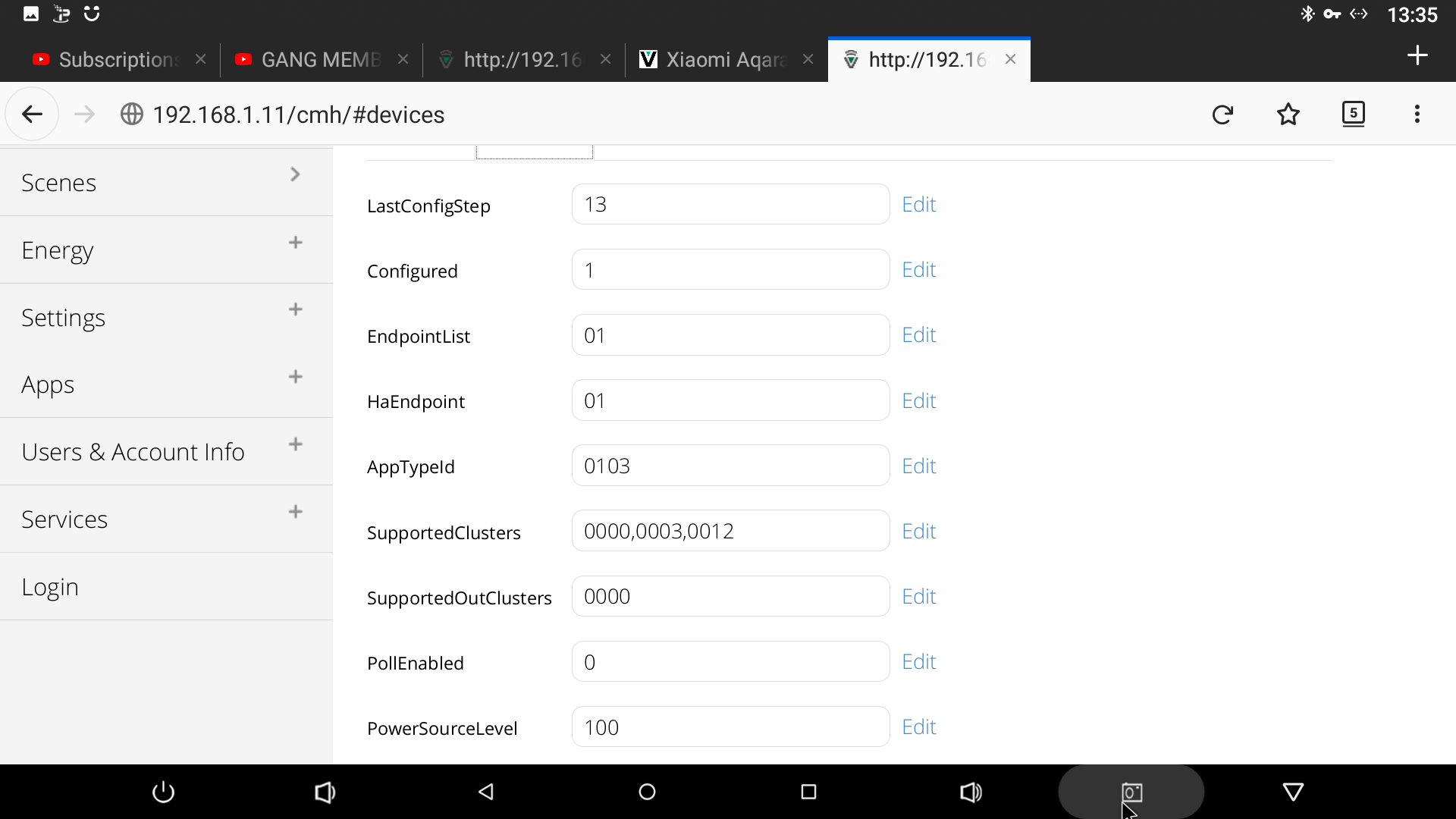
tried 0000,0003,0012,0019,ffff,0005,0406
on the other hand this did help me get my xoaomi round temp/humidity sensr working and displaying reading
I will keep trying with button, still open to any suggextions
That’s good news, want to share a short ”how to”?
Xoaomi round temp/humidity sensor
Add device and allowed it to auto configue, while configuring press button every 2 seconds till finished.
Go to advance setting and turn auto configuration off, set to 0.
Go to adavanced - params change d_genericIO1.xml to D_TemperatureSensor1. Do same for json.
Reload luup engine and refresh browser.
Goto advanced - variables change supported clusters to 0000,0402,0405. Change ConfiguredClusters to 0000=1,0402=1,0405=1.
Reload luup and refresh browser.
Now you should have one device that displays temp and in variables there should be CurrentLevel var that is the humidity.
3 Likes
so what im trying to figure out it how thee Configuredclusters are mapped
After much reading and testing i have come to a conclusion, that vera only supports these clusters
Basic Cluster (0x0000)
Binary Input Cluster (0x000F)
Electrical Measurement Cluster (0x0B04)
Fan Control Cluster (0x0202)
IAS Zone Cluster (0x500)
Level Control Cluster (0x0008)
On/Off Cluster (0x0006)
Power Config Cluster (0x0001)
Relative Humidity Cluster (0x0405)
Temperature Measurement Cluster (0x0402)
Thermostat Cluster (0x0201)
and the button revisions all have cluster 0012. The revisions with 0006 may register off and on, but not hold or tap.
		// Aqara Button - model WXKG11LM (original revision)
		fingerprint deviceId: "5F01", inClusters: "0000,FFFF,0006", outClusters: "0000,0004,FFFF", manufacturer: "LUMI", model: "lumi.sensor_switch.aq2", deviceJoinName: "Aqara Button WXKG11LM"
		// Aqara Button - model WXKG11LM (new revision)
		fingerprint deviceId: "5F01", inClusters: "0000,0012,0003", outClusters: "0000", manufacturer: "LUMI", model: "lumi.remote.b1acn01", deviceJoinName: "Aqara Button WXKG11LM r2"
		// Aqara Button - model WXKG12LM
		fingerprint deviceId: "5F01", inClusters: "0000,0001,0006,0012", outClusters: "0000", manufacturer: "LUMI", model: "lumi.sensor_switch.aq3", deviceJoinName: "Aqara Button WXKG12LM"
		fingerprint deviceId: "5F01", inClusters: "0000,0001,0006,0012", outClusters: "0000", manufacturer: "LUMI", model: "lumi.sensor_swit", deviceJoinName: "Aqara Button WXKG12LM"
So other models may have some functionality, but not the model i purchased lumi.remote.b1acn01.
We need Vera to update the zignee stack.
1 Like
yeah i had support put a ticket it to get the zigbee stack updated, i guess we would have to hound them on there to see if we can make this happen. i understand that the support team has limitations but we need at least one person with interest in Zigbee
how do you put a support ticket in, as i will add my voice.
+1
Honestly, considering all the effort and work (you have) done here, I would eventually expect them to add native support for these devices. I understand that ZWave is their primary target because it affects all their customers, but those with VP or VS should be considered too.
\if we get s stack updat in the next firmware then a lot of the stuff will just work
Hi, just a quick post re: vera plus (EU) and aquara temp/humidity sensor (square one) :
- I was running firmware 7.29 and when I tried adding a new generic zigbee device, I always ended up getting one “genericIO zigbee device” but no child devices. Variables displayed temp and humidity. Manually adding child devices proved unsuccessful. Tried all of it multiple times, deleting devices/adding again…
- I updated to 7.31beta 2 and got both parent and child devices on the first go (holding button for 3 seconds then short-pressing when “configuring”. It still shows as not configured but I have the 3 devices and can use all the other tricks in this thread.
If it can save someone a few hours